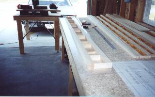
This is the construction phase of the spars. Here you
can see one of the outboard forward main spars
in the frame stage. The spars in the right of this photo are
the rear outboard spars. Note the color
difference on the inside of the spars on the right. This is due to an
epoxy coating to seal the
wood.
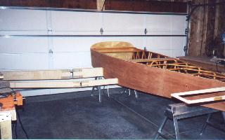
After an EAA Technical Counselor inspected my spars and the fuselage, I installed the spar webbing
(plywood skins) and then installed theWAF's
(wing attach fittings) and tried them all on for size. Everything went together as planned and I
considered this to be a milestone in the construction
process.
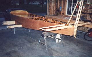
Here the firewall has been installed. The horizontal
stabilizer framed. The elevator spar cut,
hinged and test fitted. The vertical stabilizer partially framed.
The rudder spar cut, hinged and test
fitted.
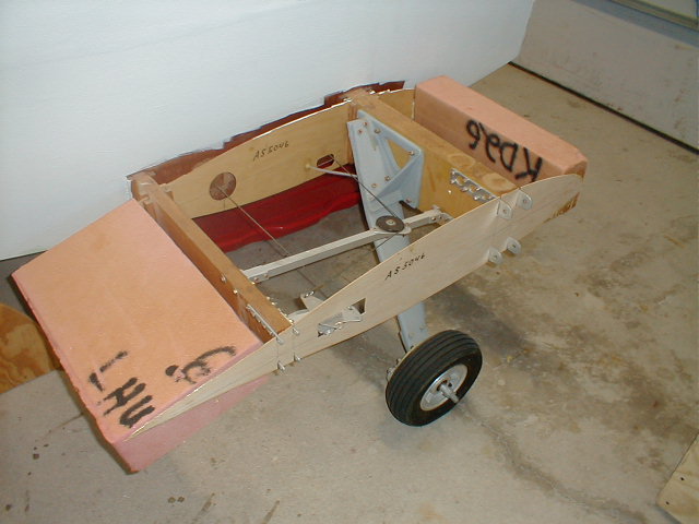
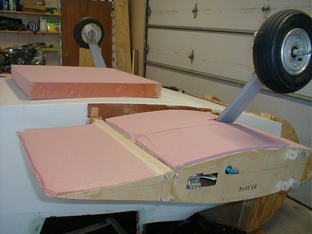
Left wing stub showing main gear leg and mounting
plate of the Diehl tri-gear arrangement. Also, a good view of the wing attach fittings (WAF's). You are also able to
see the extra support rib installed for the
wing walk area.
Left wing stub showing wing walk being constructed. I
installed a support rib just to the outside of
the landing gear pad. The cross members are 1/4" x 2" x 11" spruce. All cross members are blocked with 5/8" x 5/8"
spruce in each corner. The top is then covered
with 3/32" birch plywood. Do not forget to offset the support
ribs by 3/32" to allow for flush fit of the
3/32" plywood skin. This set up will give you more than enough
support for one sturdy wing walk area.
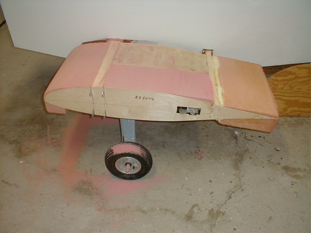
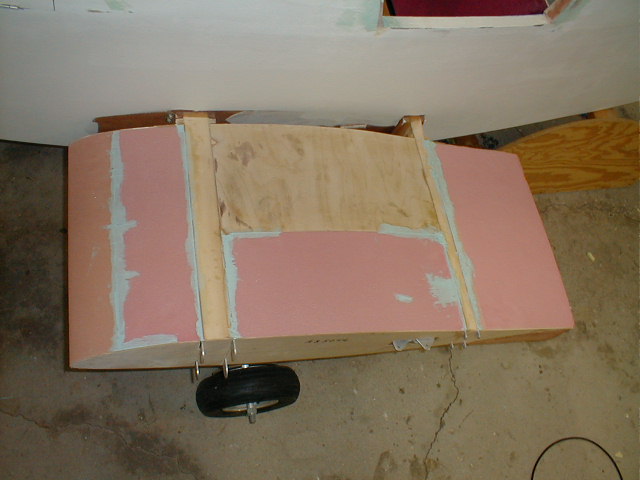
Here I am beginning to foam up the right stub
wing.
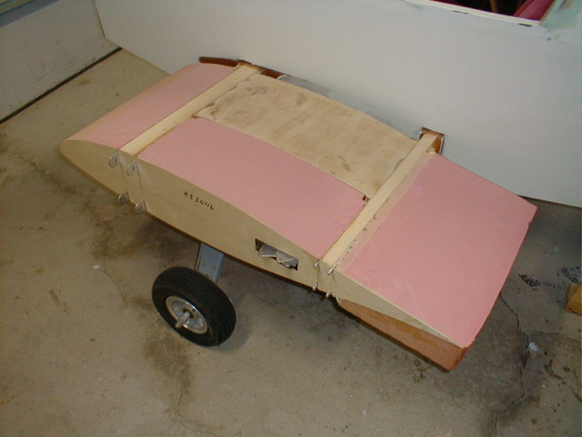
This is a shot of the left stub wing befor sanding foam to final shape.
The left upper stub wing after sanding the foam to the final shape prior to
glassing.
A little Super Fil was added to fill in some of the voids and low spots.
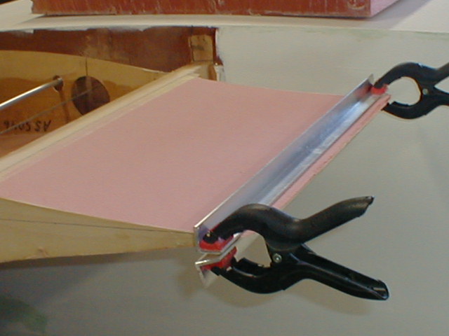
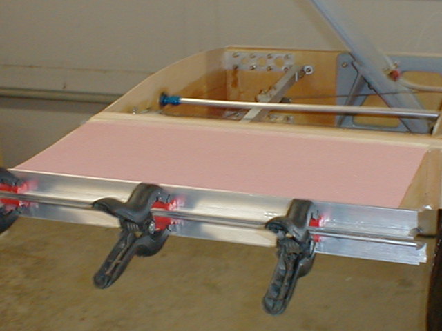
Foam is being shaped to lower stub wing
contour.
Here the aluminum angle is being used to trin the edge
straight. I used my dremel tool to do the
trimming along the edge of the angle aluminum.